Foundation Connection & Hold-Down Anchoring for LGS Modular Buildings: The 2026 Specifier's Guide
Specify LGS modular foundation anchoring with a six-option comparison, tolerance checks and a buyer checklist. Request project coordination from GFK Commercial.
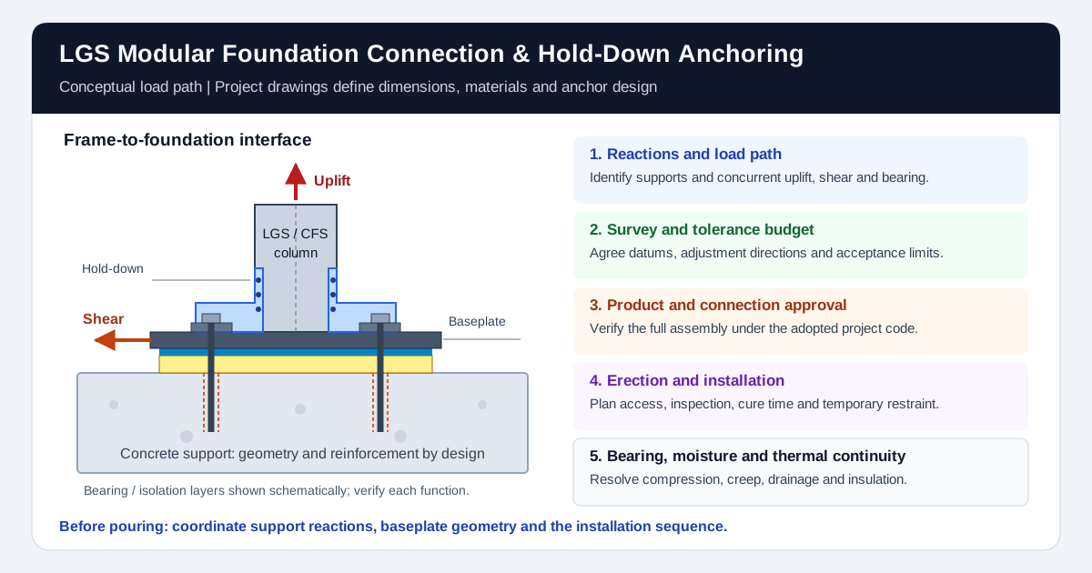
Concept diagram only: dimensions, materials, anchor quantities and temporary stability must be resolved in project drawings.
LGS modular foundation anchoring connects the factory-built frame to the site foundation and transfers compression, uplift and lateral shear into the ground. For developers, procurement managers and engineers, the first purchasing decision is which party owns that complete interface. A modular building quotation and an anchor catalogue do not establish an approved foundation connection.
Before pouring concrete, obtain a coordinated support reaction schedule, baseplate geometry and an agreed installation sequence. Confirm that the local foundation designer and modular supplier are working from the same drawing revision. This prevents a commercially attractive module purchase from leaving unresolved foundation work on the site contractor's critical path.
Reviewed: 5 November 2026. Scope: global procurement and specification guidance for light gauge steel (LGS), also called cold-formed steel (CFS), modules on concrete supports. North American and Australian standards below illustrate different approval pathways. New Zealand, UK, European and other projects need their own locally adopted requirements. This guide supplies a coordination method, not anchor capacities, construction drawings or a site-specific structural design. No project performance records are presented as customer evidence.
If your foundation package is still being scoped, send GFK Commercial your project location and module brief and ask which interface documents and local engineering services are included in the proposed supply.
1. Understand the complete foundation load path
Distributed supports and discrete reactions
Some volumetric modules transfer loads through corner columns and intermediate chassis supports. Others bear on wall lines or rails. Flat-pack LGS systems may use continuous bottom tracks with discrete hold-downs at braced wall ends. The word “modular” does not establish the support arrangement, and site-built framing can also have concentrated overturning reactions.
Start with the actual structural drawings. Trace each load path from the roof and floor diaphragms through bracing, chord studs, chassis members, brackets and baseplates into anchors, concrete and foundations. A stronger anchor cannot compensate for an inadequate screw group, a flexible plate or an unresolved foundation reaction.
A foundation reaction schedule should identify each support by grid reference, with units, sign convention, support elevation and load-combination basis. Ask for both strength and serviceability information where needed. The foundation engineer must know whether reactions are factored or unfactored and which forces occur together. Combining the largest independent tension, shear and moment from unrelated cases can give a misleading connection demand.
Hold-down anchoring is an assembly check
Keep the steel-to-steel and steel-to-concrete checks connected. The hold-down bracket, its fasteners and the supporting stud configuration must match the proposed detail. Plate bending and eccentricity can change anchor demands. The concrete design also depends on the anchor group, member geometry, reinforcement and support conditions.
Procurement rule: request the governing connection calculation and drawing reference, rather than accepting a single catalogue “kN rating.” Do not compare allowable loads, characteristic resistances and factored design strengths as though they were the same quantity. Require the designer to identify the governing limit state and the basis of each submitted value.
2. Reconcile factory and site tolerances before crane day
A precision factory assembly and an acceptable concrete pour can still be incompatible when their datums, hole geometry or support elevations differ. Avoid assigning a universal factory tolerance or quoting a concrete standard as permission for every interface deviation. Establish the project acceptance limits in the coordinated drawings and inspection plan.
A practical tolerance budget
Map four sources of mismatch: fabrication of the chassis and baseplate; setting out and placement of cast-in items; concrete support elevation and edge location; and module positioning during erection. Include survey uncertainty and movement during setting. Allocate an adjustment method to each direction rather than assuming one longitudinal slot solves every mismatch.
Illustrative geometry, not a design recommendation: an ideal 16 mm round rod centered in a 22 × 45 mm slot has nominal center travel of (45 − 16) / 2 = 14.5 mm along the slot and (22 − 16) / 2 = 3 mm across it. These are geometric clearances before installation allowances. They are not approved adjustment limits, a washer design or an anchor resistance calculation. This simple check explains why a long slot offers little adjustment across its width.
If slots are proposed, the connection designer must resolve the plate and washer arrangement, slip, bearing, uplift and shear transfer. Tightening a nut does not automatically establish a designed friction connection. A field weld changes the connection and needs an approved weld detail, suitable materials, access, inspection and coating repair; it is not a routine remedy for misalignment.
Cast-in versus drill-after-setting sequencing
Cast-in anchors can be appropriate when templates, reinforcement coordination and survey control are reliable. Check position and projection before the pour and again before module delivery. Include a hold point for discrepancies while a repair remains accessible.
Post-installed anchors can reduce clashes with protruding rods during setting. They still need adequate concrete geometry, reinforcement clearance and access for drilling, cleaning, injection, inspection and tightening. Scanning does not authorize cutting reinforcement or prestressing tendons. Obtain engineering direction if a proposed bore conflicts with embedded items.
Most critically, post-installed anchorage is not available simply because the module has landed. Plan how the module resists erection wind and other temporary actions before the permanent connection becomes effective. Crane release, temporary restraint removal and loading of new anchors are separate approval decisions in the erection plan.
3. Compare six foundation anchoring options
Use this table to compare coordination requirements, not to rank generic anchor strengths. Capacity, cost and programme depend on the selected product, geometry, design loads and installation conditions; there is no reliable universal kN or cost multiplier for an anchor type.
| Anchoring option | Coordination advantage | Main design question | Site hold point | Procurement evidence |
|---|---|---|---|---|
| Cast-in headed or hooked anchors | Can be positioned before module delivery | Does the designed anchor group work with the concrete edges, reinforcement and baseplate? | Survey before pour and before setting | Approved template, anchor specification and as-built survey |
| Post-installed adhesive anchors | Hole positions can follow an approved surveyed layout | Is the exact system suitable for the concrete, loads, temperature and installation method? | Installation inspection and full cure before the specified loading | Evaluation report, installation instructions and installation records |
| Post-installed concrete screw anchors | No adhesive cure interval | Are embedment, concrete condition, edge spacing and any reuse restrictions satisfied? | Verify the specified drilling and installation procedure | Product-specific evaluation and approved design |
| Cast-in plates with headed studs | A flush plate can avoid projecting bolts | Are plate bending, stud transfer, welding and concrete resistance resolved? | Embed survey and approved welding inspection | Embed drawings, calculations, weld procedure and coating repair detail |
| Post-installed undercut anchors | Mechanical engagement can suit selected engineered applications | Are the product qualification, undercut geometry and member dimensions suitable? | Verify the required tooling and installation checks | Product evaluation, anchor design and installer method |
| Through-bolted or sleeved beam details | May suit supports with planned access to both faces | Can local bearing, splitting, sleeve treatment and long-term access be resolved? | Inspection before access is closed | Engineered beam and plate detail, access plan and installation records |
For all six options, review the foundation itself. Passing an anchor calculation does not verify soil bearing, sliding, overturning or the capacity of an existing slab. A thin slab-on-ground should not be treated as a suitable concentrated module support without assessment.
4. Establish the project code and product approval basis
North American projects
The local jurisdiction determines the adopted building code and referenced editions. The official ACI CODE-318-19(22) publication record identifies Chapter 17 as “Anchoring to Concrete.” Its scope includes mechanical and adhesive anchoring, inspection and construction documents. This is an edition reference, not a claim that every 2026 project uses that edition.
Ask the engineer to coordinate the applicable CFS member and connection provisions with the anchorage design. An evaluation of the adhesive does not verify the bracket, stud screws or chassis. Avoid mixing strength-design demands with allowable-stress tables without the designer establishing a consistent basis.
As a product-specific example, ICC-ES ESR-4057 for Simpson Strong-Tie SET-3G, reissued April 2026, covers specified anchor applications in cracked and uncracked concrete, including wind and seismic tension and shear within its conditions. It is evidence about that evaluated system, not an endorsement of a modular supplier or an approval for every concrete support.
Australia and other jurisdictions
The Standards Australia AS 5216:2026 record lists the standard for design of post-installed and cast-in fastenings in concrete. Published on 10 April 2026, it supersedes the 2021 edition. Publication and project adoption are different: have the responsible engineer confirm the edition required by the applicable approval and contract.
For Australian work, also resolve the applicable action, CFS and concrete design requirements. Do not automatically apply this Australian pathway to New Zealand. In the UK and Europe, ask for the applicable national standards, National Annexes and product assessment documentation. An ETA and an ICC-ES report are different documents; neither transfers compliance automatically between jurisdictions.
Review failure modes without inventing a capacity
Require the connection calculation to address applicable steel failure, concrete breakout, pull-out or bond, splitting, pry-out and combined tension–shear effects. Which checks govern depends on anchor type and configuration. Concrete edge distance, spacing, embedment, thickness and cracking condition must be stated explicitly. A generic rule such as “eight rod diameters from the edge” cannot replace the approved product limits and design calculation.
5. Detail bearing, moisture separation and thermal continuity
Bearing and grout
The drawings should identify the permanent bearing arrangement: engineered pads, grout, shims or another designed support. Do not assume that all shims are temporary or that every module needs the same grout bed. Where grout is specified, coordinate its properties, permitted thickness, substrate preparation, placement, inspection and strength needed before loading.
A gap below a baseplate can affect anchor bending and the shear-transfer detail. The foundation designer and chassis designer must agree how shear crosses the interface. Grout compressive strength alone does not establish that load path, and “non-shrink” is not permission to ignore installation and curing instructions.
Moisture and corrosion
Detail drainage, flashing and a suitable capillary break where required. Concrete moisture, trapped water, steel coating selection and exposure conditions need to be considered together. Avoid selecting a rod coating or stainless grade solely from a fixed distance to the coast. Specify compatible fasteners, contact materials and coating repair for the actual environment.
A damp-proof course beneath a wall track has a different role from a structural bearing pad below a concentrated column reaction. Any membrane within a loaded bearing interface needs to be compatible with the connection design. Check penetrations and flashing continuity so that anchors and access panels do not create a concealed water path.
Thermal breaks
A moisture membrane is not automatically an effective structural thermal break. If a thermal break is needed beneath a baseplate, assess compression, long-term creep, slip, temperature, durability and relevant fire performance alongside thermal conductivity. Coordinate insulation continuity and condensation risk with the envelope designer; no single pad property establishes whole-building energy compliance.
6. Specifier's procurement and installation checklist
Use the following checklist as release gates. Record the responsible party, drawing revision and sign-off for each item. A supplier statement that a unit is “foundation ready” should not replace the evidence.
Before the foundation pour
- Support reactions: obtain the support layout, compression, uplift, shear and moment information, units and governing concurrent load cases.
- Geometry: coordinate the baseplate, holes, anchor projection, concrete edges, reinforcement, support elevations and access zones.
- Design basis: name the adopted code editions, product evaluation documents and party responsible for local engineering approval.
- Tolerance plan: agree survey datums, acceptance limits, templates, adjustment details and the process for resolving a mismatch.
Before module delivery and crane booking
- As-built survey: compare measured foundations and cast-in items against approved interface drawings; close discrepancies before dispatch or lifting.
- Hardware package: match the anchor, rod, nut, washer, bracket and fasteners to the approved design; record permitted substitutions.
- Installation access: verify drilling and inspection access, equipment clearance and safe access after the module is placed.
- Temporary stability: obtain the erection sequence, restraint arrangement, weather limits and criteria for releasing the crane.
During anchoring and handover
- Bore preparation: follow the selected system's drilling and cleaning procedure, including the approved equipment and hole condition; do not substitute a generic blow–brush count.
- Adhesive record: log product batch, expiry, concrete temperature, moisture condition, installation time and required cure completion.
- Bearing and tightening: verify the bearing detail, grout or pad readiness and the product-specific tightening procedure with suitable calibrated equipment.
- Closeout: retain inspection records, approved deviations, as-built anchor positions and any required testing before access is closed.
One scheduling example shows why the cure hold point matters. ESR-4057 Table 9 lists a 24-hour cure at 21°C concrete temperature and 192 hours at 5°C, with cure times doubled for water-saturated concrete. Those values belong to the identified SET-3G report and conditions; they are not a schedule for other adhesives. Gel time describes a different installation limit. Establish temporary restraint and loading decisions from the actual approved system and conditions.
For a supply comparison, ask GFK Commercial which coordination documents can be included in your quotation. Attach this checklist and request an explicit list of exclusions, especially foundation design, local certification, temporary works and site inspection.
7. Worked planning examples: test the interface and the allowance
These are hypothetical procurement exercises, not GFK Commercial projects, measured site results or anchor designs. Their purpose is to show how a buyer can challenge an incomplete installation proposal without treating an illustrative number as engineering evidence.
Example A: a slot does not absorb every survey error
Assume the illustrative 22 × 45 mm slot and 16 mm rod from Section 2. A survey finds a rod center 8 mm across the slot width from its intended position. The ideal 3 mm transverse center travel is smaller than that offset, even though the slot is 45 mm long. The next action is an engineering query and an approved resolution before lifting. Rotating, elongating or flame-cutting the slot on site is not authorized by this calculation.
Request the actual survey coordinates, hole drawing and acceptance criteria with the query. Record whether the resolution changes the baseplate, anchor location, foundation or setting position, and which party approves it. That makes the discrepancy reviewable before a crane is booked.
Example B: a transparent delay allowance
Assume a buyer's planning allowance uses a crane standby rate of USD 400 per hour, a six-person crew at USD 50 per person-hour, and four hours of delay. The direct allowance is (400 × 4) + (6 × 50 × 4) = USD 2,800. These are invented inputs for arithmetic, not market rates or a supplier quotation.
The allowance excludes remobilization, revised engineering, replacement hardware, accommodation, access permits and contractual delay costs. Obtain local rates and price those items separately. Compare complete installed proposals: cast-in work may need templates and survey effort; post-installed work may add drilling, inspection and cure-related temporary works. The cheaper hardware line is not necessarily the lower installed cost.
8. Next steps: define the foundation interface in the RFQ
Send a single coordinated request for quotation with the project location, building use, module arrangement, proposed support system and available site drawings. Ask for a named interface owner and a document schedule. Identify when preliminary reactions become final, how design changes are notified and whether foundation work can proceed on the information supplied.
For GFK Commercial supply enquiries, request a project-specific coordination discussion. Ask which baseplate drawings, reactions and hardware information are available for your selected model, and confirm the scope of any local engineering separately. Make agreed deliverables part of the contract before relying on them for a concrete pour or crane booking. You can also return to GFK Commercial's product articles or the blog index for further reading.
9. Frequently asked questions
Why can foundation bolt alignment delay modular installation?
A factory baseplate and a site foundation can each meet their own tolerances while their holes still fail to align. Agree a shared survey datum, an interface tolerance budget and an approved adjustment detail before fabrication and the concrete pour.
Do all LGS modules transfer loads through four corner anchors?
No. Some chassis use discrete columns; other modules bear along walls, rails or intermediate supports. Require a support layout and reaction schedule for the selected system, including concurrent uplift, shear and compression load cases.
Are chemical anchors suitable for wind and seismic loading?
They can be, when the exact anchor system is evaluated for the concrete condition and loading, and the engineer verifies the connection under the locally adopted code. An ICC-ES report or ETA does not by itself approve a modular building or transfer approval between jurisdictions.
How long must an adhesive anchor cure before loading?
Use the selected product instructions and evaluation report for the actual concrete temperature and moisture condition. Gel time is not cure time. Keep the module stable under an approved temporary works plan until the required anchorage is ready for the intended load.
Can a DPC membrane also act as a structural thermal break?
Do not assume so. Moisture separation, structural bearing and thermal performance are separate requirements. Any layer under a loaded baseplate needs an engineered detail that addresses compression, creep, slip and compatibility with the anchorage.
What should buyers obtain before foundations are poured?
Obtain coordinated support reactions, baseplate and anchor geometry, the project design basis, product evaluation documents, a survey and tolerance plan, and a responsibility matrix. Identify who provides local engineering approval, temporary stability and installation inspection.
Sources & references
Sources checked on 5 November 2026. Standards catalogue records establish publication identity and scope; project compliance requires the applicable full standards, design calculations and current product instructions. None of these sources validates the illustrative costs, slot design or supplier service claims.
- ACI CODE-318-19(22): Building Code Requirements for Structural Concrete and Commentary — official publication record and table of contents, including Chapter 17 and inspection documentation. Confirm the project-adopted edition.
- Standards Australia: AS 5216:2026 — official publication record, dated 10 April 2026, for concrete fastenings; supersedes AS 5216:2021. Catalogue status does not determine statutory adoption.
- ICC-ES ESR-4057: Simpson Strong-Tie SET-3G epoxy adhesive anchors — April 2026 report, especially Sections 2 and 5, installation requirements and Table 9 cure schedule. Product-specific evidence, not blanket modular-building approval.
Author

Categories
More Posts

Australia Modular Housing Market Update: NSW Approval Changes and Easter Delivery Curfews
Australia modular housing update for 1 April 2026: NSW 14-day modification rules and NHVR Easter curfews reshape approval and delivery decisions.
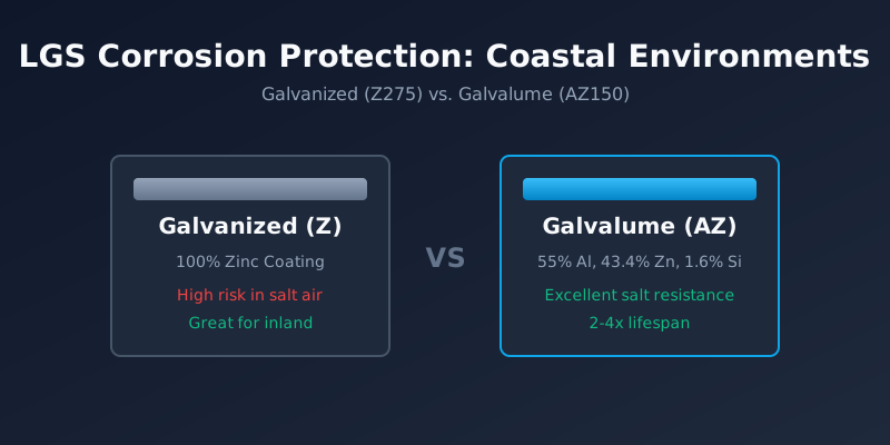
Corrosion Protection in LGS Modular Construction: Galvanized vs. Galvalume for Coastal Projects
An engineering and procurement guide to specifying the correct steel coating for Light Gauge Steel (LGS) modular buildings in coastal environments. Compare Z275 Galvanized vs. AZ150 Galvalume.
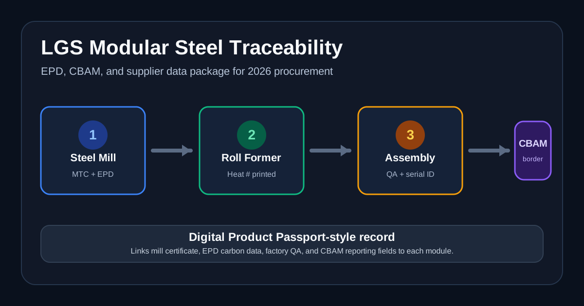
LGS Modular Steel Traceability: Navigating EPDs and CBAM in 2026 Procurement
A 2026 procurement guide to Light Gauge Steel (LGS) modular traceability. Master CBAM compliance, Environmental Product Declarations (EPDs), and supplier verification for cross-border imports.